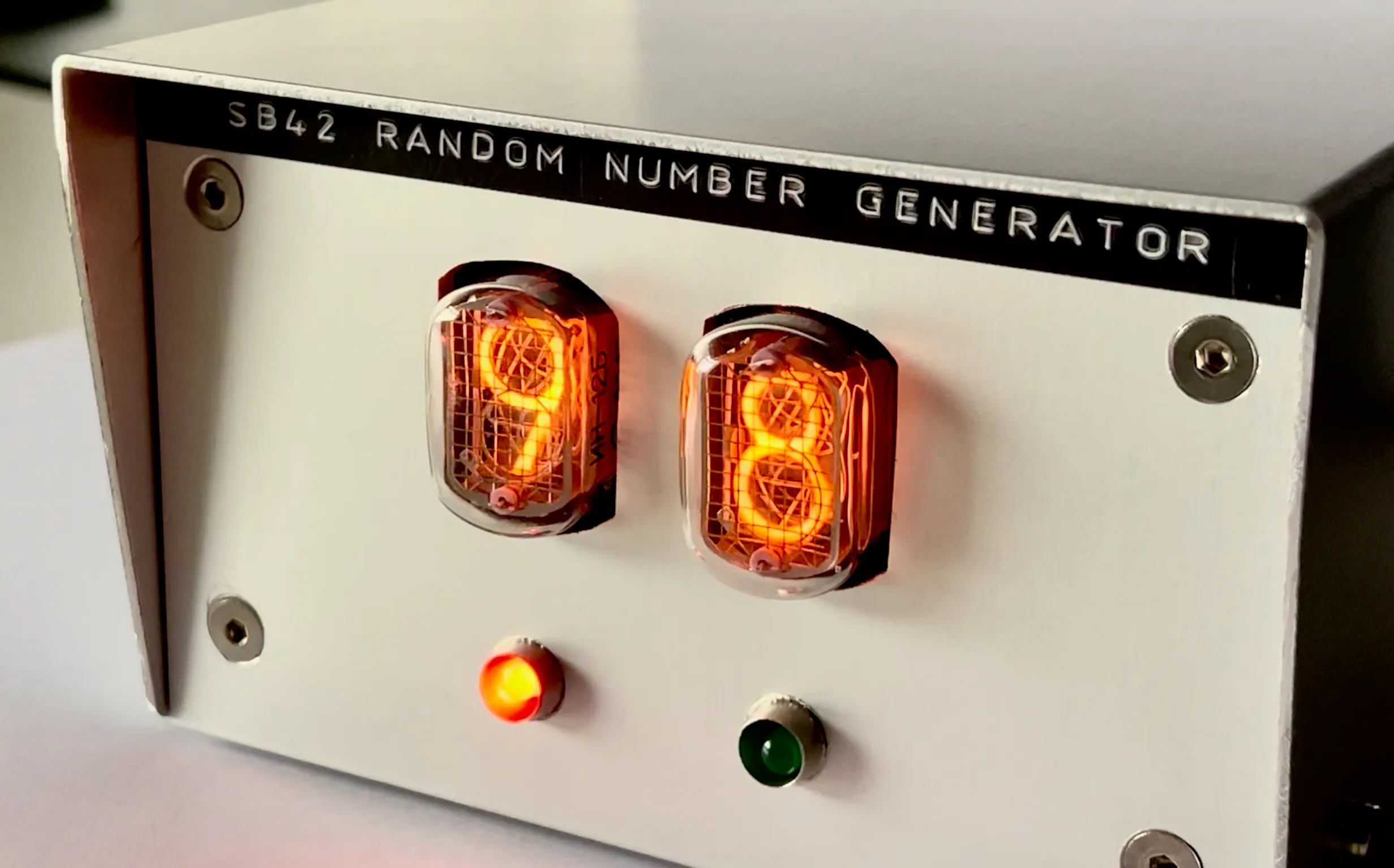
SB42 Random Number Generator
I was intrigued by Dev Gualtieri’s project for Circuit Cellar which can generate pseudo-random numbers using a linear-feedback shift register. Connecting one up to some LEDs or even 7-segment displays gives a constant stream of random-enough-but-eventually-repeating binary digits. What I love is that this is all done with basic logic chips instead of a microcontroller.
Dev’s circuit uses a pair of 555 timers to create a series of 4 quick pulses spaced about a second apart. This moves the position of the shift register over to the next digit and holds it there for a second before the next digit.
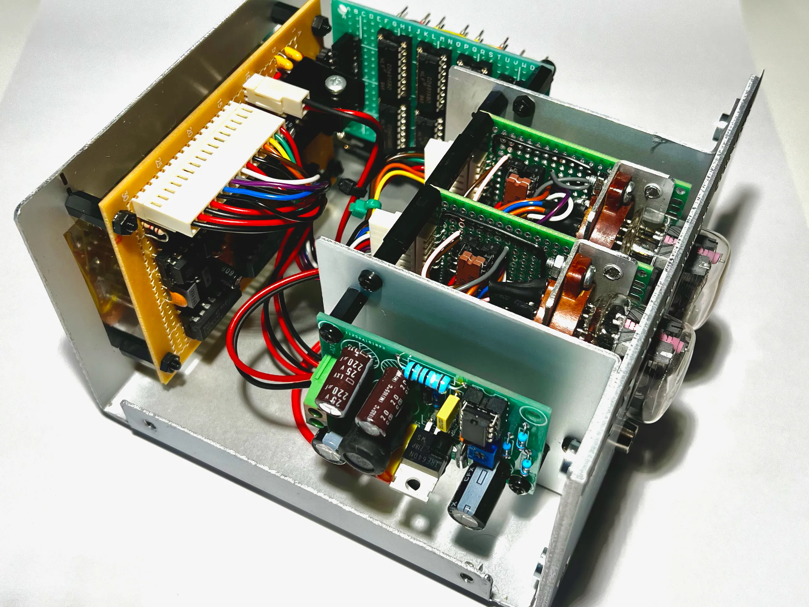
Using a pair of these linear-feedback shift registers I’m able to generate 2 separate random numbers to generate 2-digit numbers instead of just a single digit.
Instead of 7-segment displays I’ve chosen the nice warm glow of Nixie tubes. However, these Nixie tubes will only display decimal numbers in the range of 0 to 9, not the full 4 bits being generated by Dev’s circuit of 0 to 15. Digits greater than 9 will turn the displays blank. In the article Dev does mention “additional chips would solve this problem”.
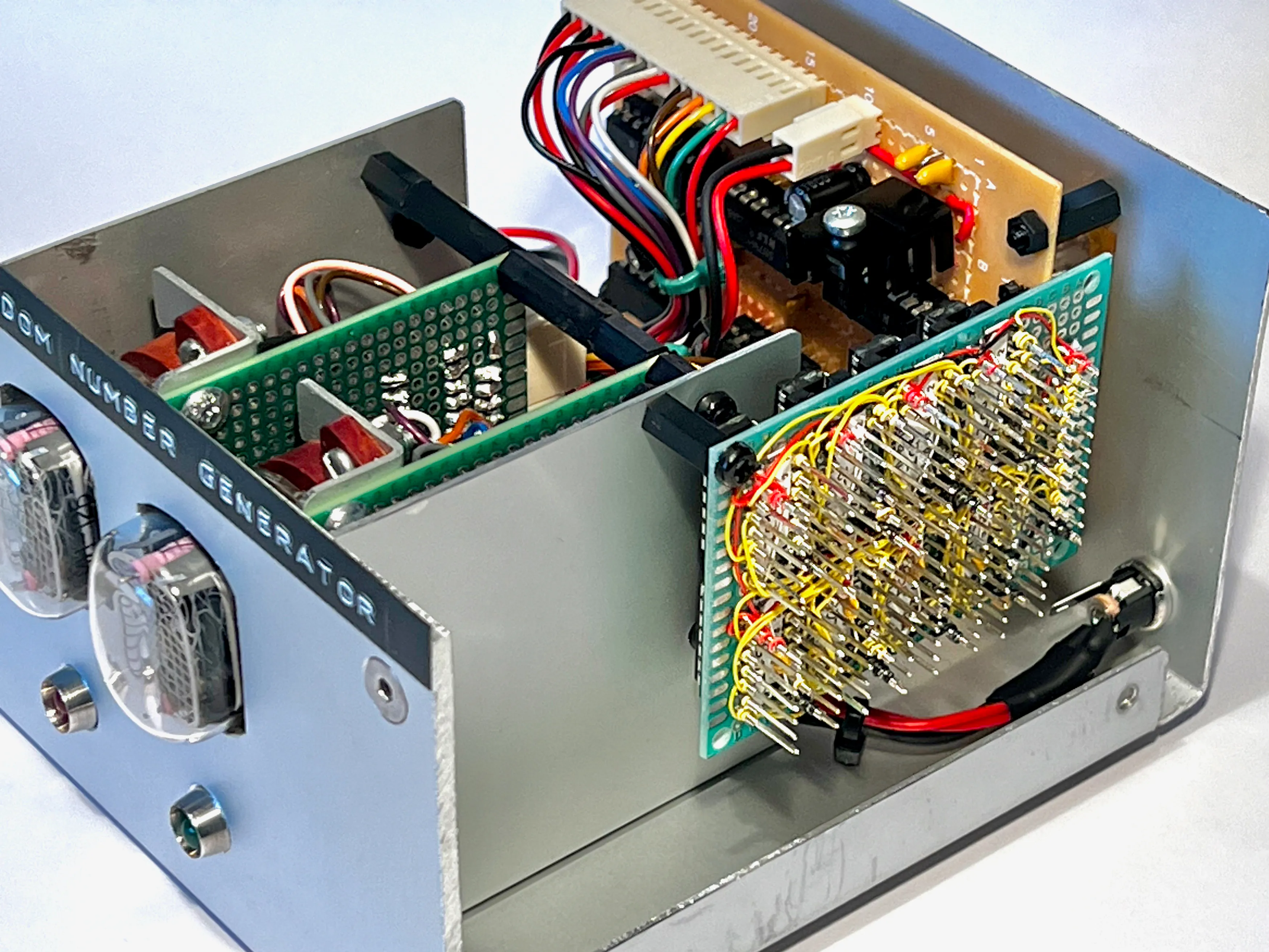
Armed with some additional chips, I increased the complexity by adding some logic gates which will only make a latch signal when the number is less than 10. Instead of the Nixie tubes directly displaying the output of the linear-feedback shift registers they display the contents of a pair of 4 bit registers. The random numbers are only latched using that logic signal into these registers when the number is in the decimal range.
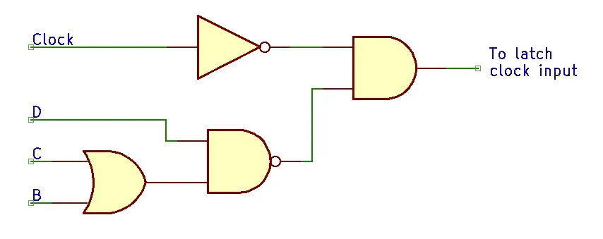
The timing is also adjusted to generate much more than 4 pulses each time to ensure that the linear-feedback shift registers have generated a valid decimal number. However, in any sufficiently random universe this will eventually generate a stream of non-decimal digits and it’ll just look like it has stuck at the same number.
This actually creates an interesting effect where you can see the 2 separate digits flickering at different rates. If a digit does not immediately change then you know it has generated a number above than 9 so has not been latched onto the displays. This gives the impression of some real deep thought going on inside.
Using a spare logic gate and a pair of LEDs I can also show whether the thing is still cycling onto the next random number (red) or has now paused at the last pair of valid decimal numbers (green).
Download the schematic