Modernising a vintage digital clock
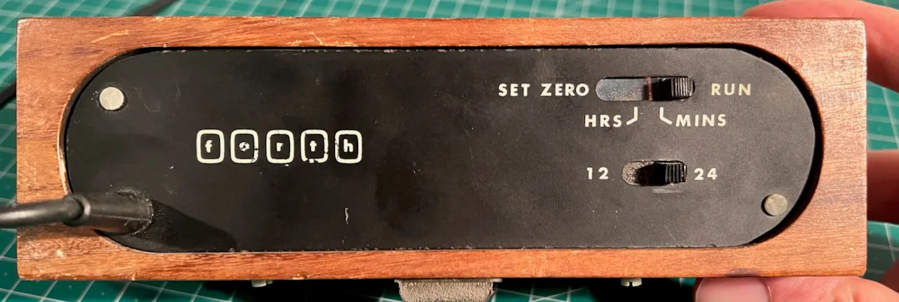
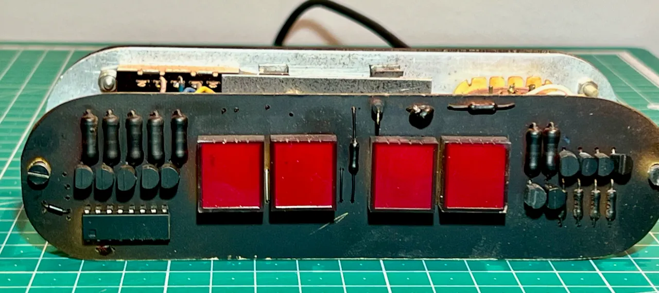
I recently picked up an interesting digital clock for only £3 at, of all places, an agricultural show. Branded “Forth” on both the back and on the PCB inside I have not been able to find any information on the manufacturer of this. The internals are nicely designed and very compact in a solid wooden case (no veneer!). There’s holes on top of the case which line up with a connector inside suggesting there may have been something like a lamp originally mounted above.
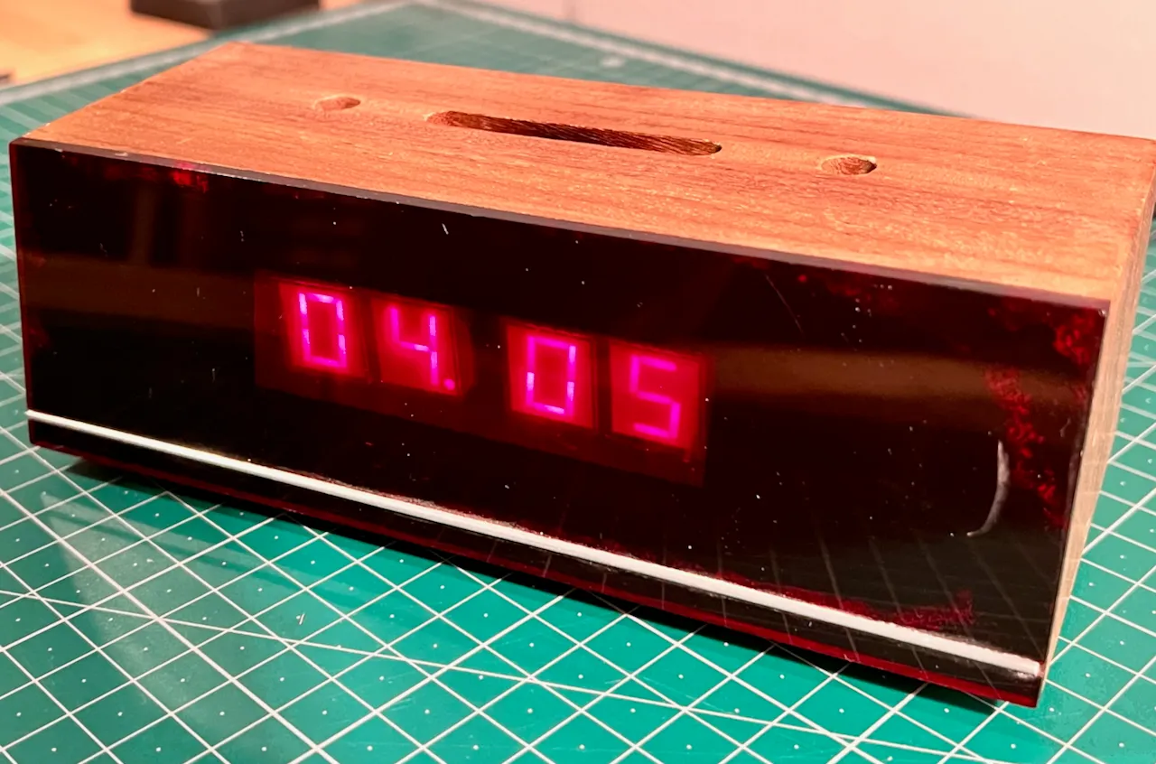
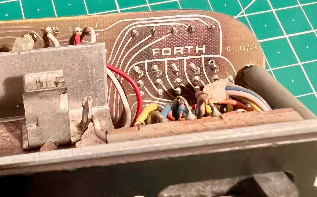
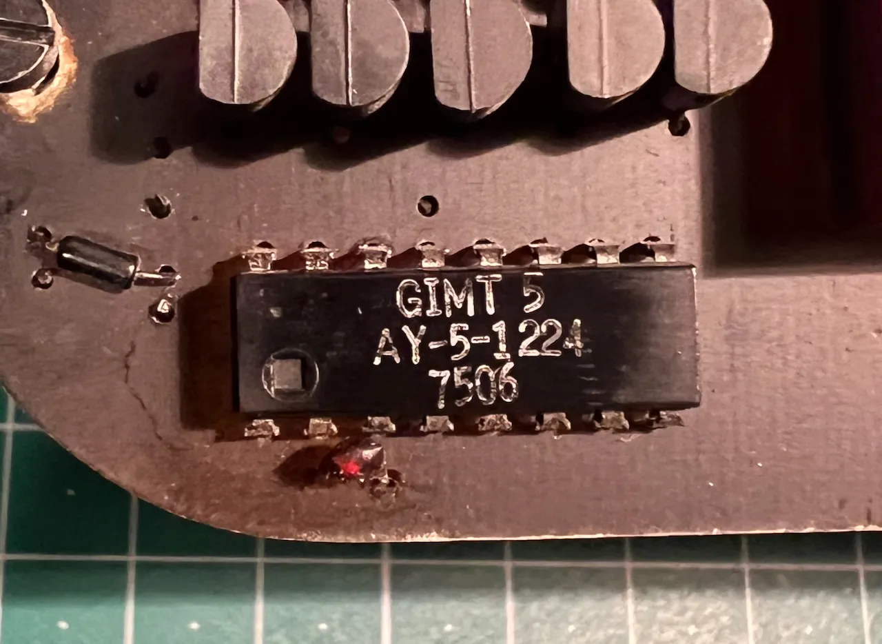
The datecode on the single IC shows this was built in the second half of the 70s. This chip is an AY-5-1224 and uses a 12V AC signal to keep track of the time—just wire the chip for 50 or 60Hz mains power—and also handles driving the four 7-segment displays. Those are red Fairchild FND500 displays, although some of the segments are now failing which could also be due to any part of the driver circuitry.
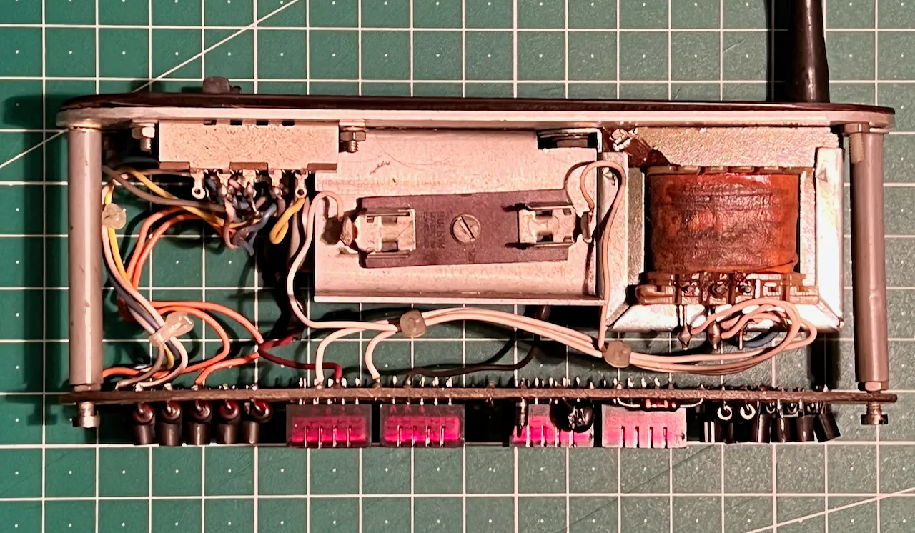
Because of the failing digits and the questionable safety of a 50 year old unearthed appliance I wanted to modernise it a bit. The original internals look so good anyway it’s a shame to keep them hidden in that case so they’ll go on display somewhere.
Using a spare first generation Raspberry Pi Zero combined with a 256×64 white OLED display I programmed up a clock animation based on the LED patterns of the Thinking Machines Corporation CM-5 supercomputer. There’s an implementation of this animation available in C and it was fairly simple to convert this into Python to create a 64×16 pixel pattern. My code for this is available on GitHub.
The OLED display I used supports 16 levels of greyscale, so the pattern is set to be less strong than the digits to make them readable. But when each minute changes, the pattern is turned to full brightness to make a more pleasing transition. This glows really nicely through the red acrylic front.
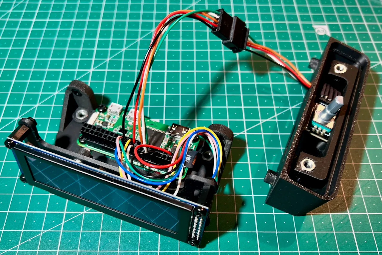
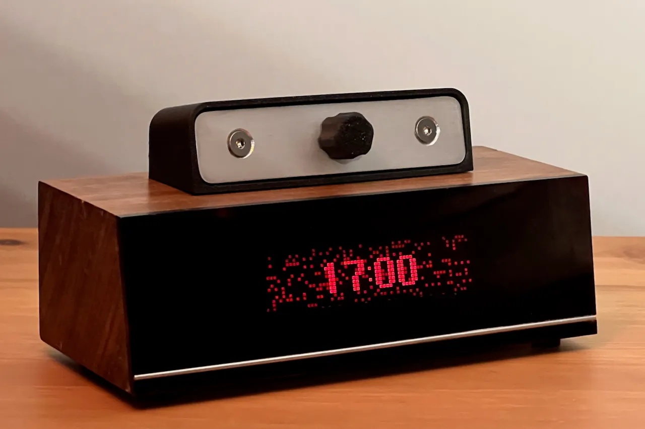
Using the existing hole in the wooden case I added a rotary encoder to give control over the speed of the animation. Pressing the rotary encoder in triggers a safe shutdown of the Pi. All the internal brackets and mounts, as well as the rotary encoder housing on top, are 3D printed to fit the woodencase without any need for customisation.